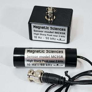
The MC95Rw sensor provides a strong response from Extremely Low Frequency (ELF) through Very Low Frequency (VLF) ranges, with a sharp high resonant peak.
The MC95Rw has 3-wire output and connector for wire-to-board or wire-to-wire applications. You can use the 3-wire connector (MTA-100 IDC) attached to ends of the wires, or you can cut it off. If connecting to a PCB or coax or other transmission line normally the red and yellow wires are used. The red or yellow can be soldered to the center conductor, and the other (red or yellow) to the outer conductor of the coax. The green wire is a center-tap, it is not necessary to use the green wire, it provides 1/2 of the voltage output to either end of the coil (green to red or green to yellow is 1/2 of red to yellow). Twisting the wires together minimizes pickup of stray fields.
We measure the output data using a 36-inch long RG-58 coax connecting the red and yellow wires to our display instrument input. That coax length gives a resonant peak near 1.5 kHz. A different coax length or no coax will shift the resonant frequency due to the different coax capacitance. If there is no coax length used between the 3-wire connector to your display instrument input, then the MC95Rw resonance is near 2.3 kHz.
The voltage output is also affected by the input impedance of the display instrument you are using. For sensors like this model MC95Rw that have a "high resonant peak" we recommend using a display instrument with input impedance of 10 MegaOhms shunted by less than 30pF, to obtain a high resonant peak and the calibrated output response.
- Frequency Range:
- 10 Hz - 50 kHz
- Option 1: Shape:
- B2 Box, rectangular
- Option 1: Size:
- 2.1" x1.6" x1.2” (52x40x29mm)
- Option 1: Connector:
- 3-wire conn. for wire-to-board & wire-to-wire
- Option 1: Weight (approx):
- 3.5 oz (99g)
- Option 2: Shape:
- C3 Cylinder, small
- Option 2: Size:
- 2.75" x 0.875” (70 x 22mm)
- Option 2: Connector:
- 3-wire conn. for wire-to-board & wire-to-wire
- Option 2: Weight (approx):
- 2.1 oz (60g)


