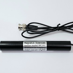
Magnetic Sensors for 5 Hz-1 MHz
These calibrated magnetic field sensors or probes are cost-effective tools to detect magnetic fields from 5 Hz to 1 MHz (any waveforms), and to accurately measure magnetic field strength of continuous-wave (CW sine wave) fields from 5 Hz to 1 MHz.
These single-axis "B-dot" coil sensors respond to magnetic fields parallel to the coil axis; they produce an output voltage calibrated to the CW magnetic field strength. You display the output voltage on your own instrument (AC or RF voltmeter, multimeter, oscilloscope, or spectrum analyzer with high input impedance). The frequency of the sensor output voltage is the same as the frequency of the magnetic field. No battery or power supply is needed for the sensors.
NIST traceable calibration certificate with data is delivered with each sensor. These are easy-to-use affordable sensors for magnetic field measurement, EMC / EMI / RFI testing, and troubleshooting. These sensors do not measure static or DC magnetic fields for example from motionless magnets or the earth's magnetic field, unless the sensor is vibrating or rotating.

| Sensor Model | Frequency Range | Frequency Response Description | ITU Bands | Price US$ | Availability | Size, Shape* |
| MC910 | 5 Hz - 600 Hz | 60 Hz peak, 20-200 Hz coverage | ELF/SLF | $ 195. | In Stock | C4 |
| MC858 | 10 Hz - 400 Hz | 58 Hz Resonant peak, 30-100 Hz | ELF/SLF | $ 95. | In Stock | B2 or C3 |
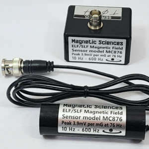
| MC876 | 10 Hz - 600 Hz | 76 Hz Resonant peak, 30-200 Hz | ELF/SLF | $ 95. | In Stock | B2 or C3 |
| MC06 | 50 Hz - 120 Hz | 61 Hz Resonant peak, small size | SLF | $ 75. | In Stock | B1wm |
| MC14 | 40 Hz - 400 Hz | 135 Hz Resonant peak, small size | SLF | $ 125. | Special order | B1wm |
| MC19 | 40 Hz - 1 kHz | 190 Hz Resonant peak, small size | SLF/ULF | $ 75. | In Stock | B1wm |
| MC95A | 10 Hz - 10 kHz | 30-3000 Hz Flat wideband 1mG=1mV | SLF/ULF/VLF | $ 195. | In Stock | B2 or C3 |
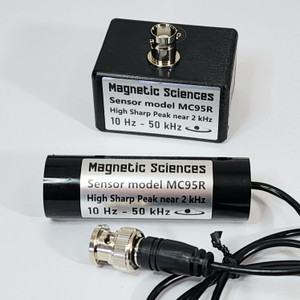
| MC95R |
10 Hz - 50 kHz | 1.5 kHz** High resonant peak | SLF/ULF/VLF | $ 125. | In Stock | B2 or C3 |
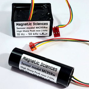
| MC95Rw | 10 Hz - 50 kHz | 1.5 kHz** High resonant peak | SLF/ULF/VLF | $ 95. | In Stock | B2 or C3 |
| MC95-220 | 10 Hz - 30 kHz | 1.5 kHz Rounded peak: wideband | SLF/ULF/VLF | $ 125. | In Stock | B2 or C3 |
| MC90R | 10 Hz - 20 kHz | 1.8 kHz** High resonant peak | SLF/ULF/VLF | $ 195. | In Stock | C4 |
| MC90-110 | 10 Hz - 20 kHz | 1.8 kHz Rounded peak: wideband | SLF/ULF/VLF | $ 195. | In Stock |
C4 |
| MC90-022 | 10 Hz - 20 kHz | 0.2-20 kHz Flat wideband 1mG=5mV | ULF/VLF | $ 195. | In Stock | C4 |
| MC110R | 2 kHz - 1 MHz | 120 kHz** High resonant peak | VLF/LF | $ 75. | In Stock | B1 |
| MC110A | 2 kHz - 1 MHz | 120 kHz Rounded peak: wideband | VLF/LF | $ 75. | In Stock | B1 |
| MC190-205 | 1 kHz - 150 kHz | 8 kHz peak | VLF | $ 75. | In Stock | C5 |
| MC160 | 1 kHz - 300 kHz | 1-300 kHz wideband 1mG=1mV | VLF/LF | $ 95. | In Stock | C5 |
| MC161 | 1 kHz - 500 kHz | 1-500 kHz wideband 1mG=1mV | VLF/LF | $ 100. | In Stock | C5 |
| MC162 | 1 kHz - 700 kHz | 1-700 kHz wideband 1mG=1mV | VLF/LF | $ 175. | In Stock | C5 |
| MC165 | 1 kHz - 1 MHz | 1-999 kHz wideband 1mG=1mV | VLF/LF | $ 295. | In Stock | C5 |
* Sensors are 1" to 5" long. Click Here for Size, Shape, & Connectors. Photos at bottom of page.
** For Sensors with a "high resonant peak" (models MC95R, MC95Rw, MC90R, and MC110R): the length of coax cable you use to connect the sensor to your display instrument can greatly affect the resonant frequency from the sensor. For more info see Impedance.
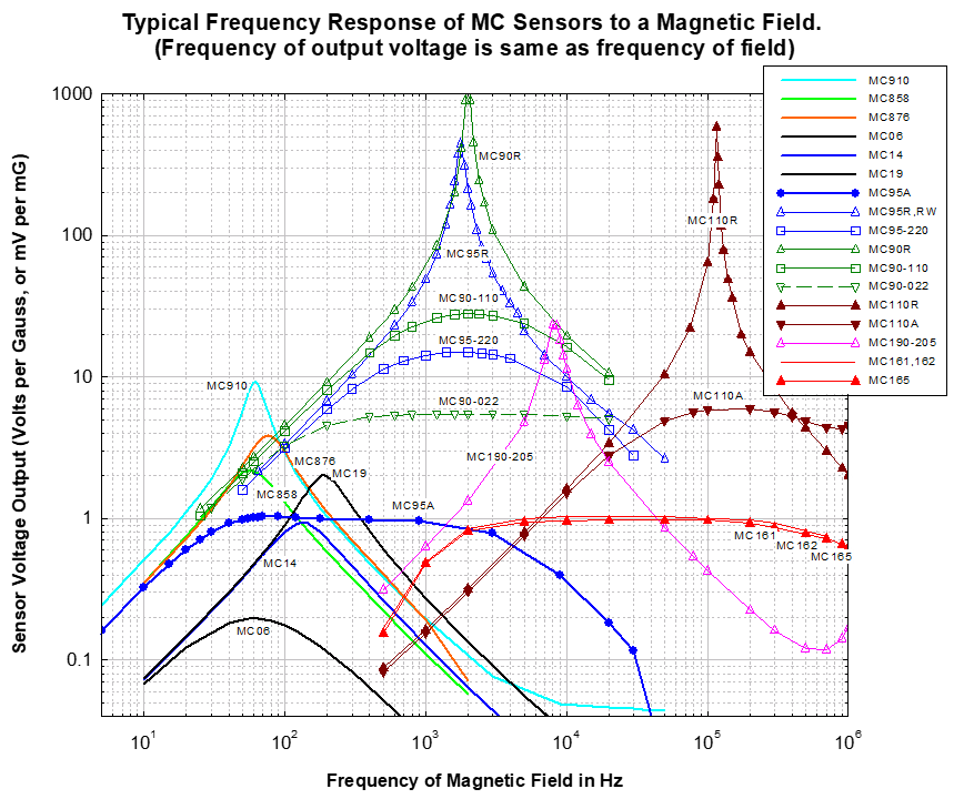
Graph above shows a curve for each sensor model, plotting the voltage output from the sensor (Volts per Gauss, or mV per mG) when the sensor is placed in a magnetic field at the frequency shown along the x axis. The graph is accurate for continuous sine wave (CW) magnetic fields. Individual sensors may vary so calibration data is also delivered with each sensor. (However, sensors with a "high resonant peak": MC95R, MC95Rw, MC90R, and MC110R, the length of cable you use to connect the sensor to your display instrument can greatly affect the resonant frequency from the sensor. For more info see Impedance.
To measure the magnetic field in Gauss: use the output voltage measured from your sensor, with the above graph or the calibration data. Here are some examples:
- Examples: at your frequency if the Volts per Gauss = 1 (on vertical axis), and you are measuring 80 mV, then the CW field = 80 mG. (80mV /1 = 80mG)
- Or, at your frequency if the Volts per Gauss = 8 (on vertical axis), and you are measuring 80 mv, then the CW field =10 mG. (80mV /8 = 10mG)
- Or, at your frequency if the Volts per Gauss = 5 (on vertical axis), and you are measuring 3 V, then the CW field =0.6 G. (3V /5 = 0.6 G)
- If your display instrument is measuring RMS volts then you are measuring RMS magnetic field strength. (RMS is recommended).
- If your display instrument is measuring Peak volts then you are measuring Peak magnetic field strength.
- Unit conversion: 10G=1mT. 1G=0.1mT=100uT. 1mG=0.1uT=100nT. 1 kA/m =1.26mT=12.6 G in air.
To Use the Sensor: Connect the sensor to your display instrument (multimeter, AC or RF voltmeter, spectrum analyzer, or oscilloscope, etc). Place the center of the sensor at the location you want to measure magnetic field strength.
The sensor is single axis and responds to the magnetic field parallel to the sensor axis, which is along the longest dimension of the sensor (parallel to the writing on the sensor label). The sensing area is along most of the length of sensor axis, so if the field is spatially non-uniform it will be averaged over the length of the sensor.
To find the maximum field polarization, turn the sensor in different directions to see the largest reading, then the sensor axis is parallel to the maximum magnetic field polarization direction. The polarization direction of the field (max reading) is often at right angles to the direction towards the source of the field.
The reading will also increase as you get closer to the source of the field, although the immediate surroundings, multiple sources, and the sensor orientation (pointing direction) can cause variations. Sometimes you won't see exactly the same reading when you check the same location again, this is usually because the sensor is not exactly at the same location and orientation. Hold the sensor still, because vibrating, shaking, or quick movements can cause extraneous readings due to sensor acceleration through the earth’s static magnetic field.
To measure the magnetic field: Measure the alternating (AC or RF) voltage output from your sensor, then reference the graph above (or the calibration data delivered with each sensor) at your frequency to determine the magnetic field strength.
Minimum Measurable Field and Resolution: These are determined by the resolution and noise level of your display instrument. The sensors are passive devices and contribute negligible thermal noise.
Maximum Field and Output Voltage: Core saturation can cause measurement inaccuracies above 50 Gauss (5 mT) field. The largest sensors (sizes C4 and C5 are 4”-5” long) may saturate at 25 Gauss (2.5 mT). Sensors may be damaged by magnetic fields producing voltage output larger than 110 Vrms for all models, except 40 Vrms max for MC95A, MC160, MC161, MC162, MC165. For all sensors a rapid change in the field can cause output voltage to peak, which can damage especially the large coils in MC90R and MC90-110. If unsure then best to gradually ramp-up and down the field strength.
Temperature Range: Sensors can operate from -30 C to + 55 C (-22 F to +131 F), or in some cases a wider temp range.
Calibration: Calibration standards and instruments are NIST traceable. Each sensor is individually calibrated using a CW sine wave magnetic field at a number of frequencies, and the calibration report with data is provided at no extra charge with each sensor. Calibration data usually remains unchanged for many years for these passive sensors. Calibration results may differ if using a different length of coax or different display instrument impedance, see next paragraph:
Instrument Impedance and Coax: To display the calibrated output voltage from the sensor we recommend you use a display instrument with high input impedance. The length of coaxial cable you use also affects measurements, especially above 30 kHz, and near high resonant peaks at any frequency, due to coax capacitance, see Impedance.
Sinusoidal and Non-Sinusoidal Fields: These sensors use a coil of wire, known as a "B-dot" magnetic field sensor or probe, since the voltage output is the time-derivative of the magnetic field. So if the magnetic field is a continuous CW sinusoidal wave (eg a sine wave), then the sensor output is a cosine CW voltage at the same frequency, and the curves in the figure above show the correct output voltage amplitude per gauss of field, at each frequency.
For non-sinusoidal waveforms the output voltage is also the first derivative (B-dot) of the magnetic field. So when exposed to a rapid large change in the magnetic field (like switching the field on or off, or a square wave, or any spikes in the magnetic field), then the sensor output voltage will show a peak or bump, since the fast change in field gives a large first derivative vs time.
Some sensors are described as "resonant" in the Description column of table at top of this page. Their frequency peak is the resonant frequency of the circuit (the sensor plus cable and input impedance of test instrument). Those resonant circuits may "ring" for a few milliseconds if briefly exposed to their resonant frequency. For example rapid changes in field from a non-sinusoidal field like a square wave can cause those resonant models to ring. So it is NOT recommended to use the "resonant" models to measure non-sinusoidal fields, due to possible distortion of the voltage output by ringing.
For screenshots of this and more measurement info see www.magneticsciences.com/measurement-notes
These sensors can also be used to detect or measure background magnetic field noise, rotations of the sensor through the earth's magnetic field, and mechanical vibrations relative to a nearby magnet.
© Copyright 2024 Magnetic Sciences Inc.


